min · typ · max

Describe the board.
Open it in KiCad.

Tell Typmax what you're building — an ESP32 with a sensor, a GPS logger, something on a LiPo. It picks real parts, wires them the way the datasheets say, and hands you a KiCad project you own.

And it shows its working. Every check comes with the arithmetic behind it — so you can see why that resistor is 4.7 kΩ, and disagree if you want to.

Join the waitlist See what you get ↓

Not open yet. Seats go out in small batches — the waitlist is how you get one.

What you get

A folder you open in KiCad.

Not a picture of a circuit. The actual project files — schematic, parts list, connections — in KiCad's own formats, yours to edit, keep and send to a board house. Nothing is locked behind a plan.

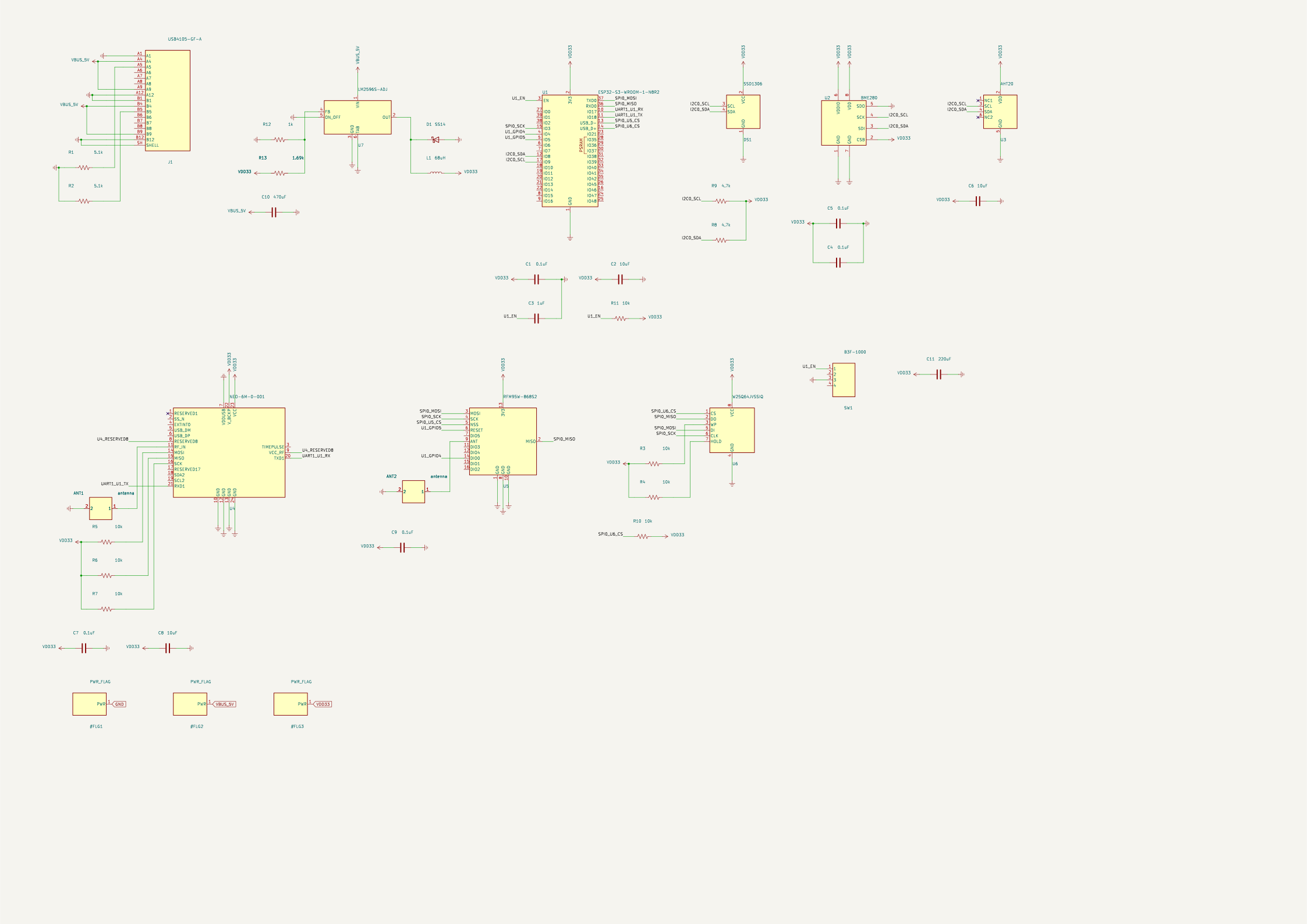
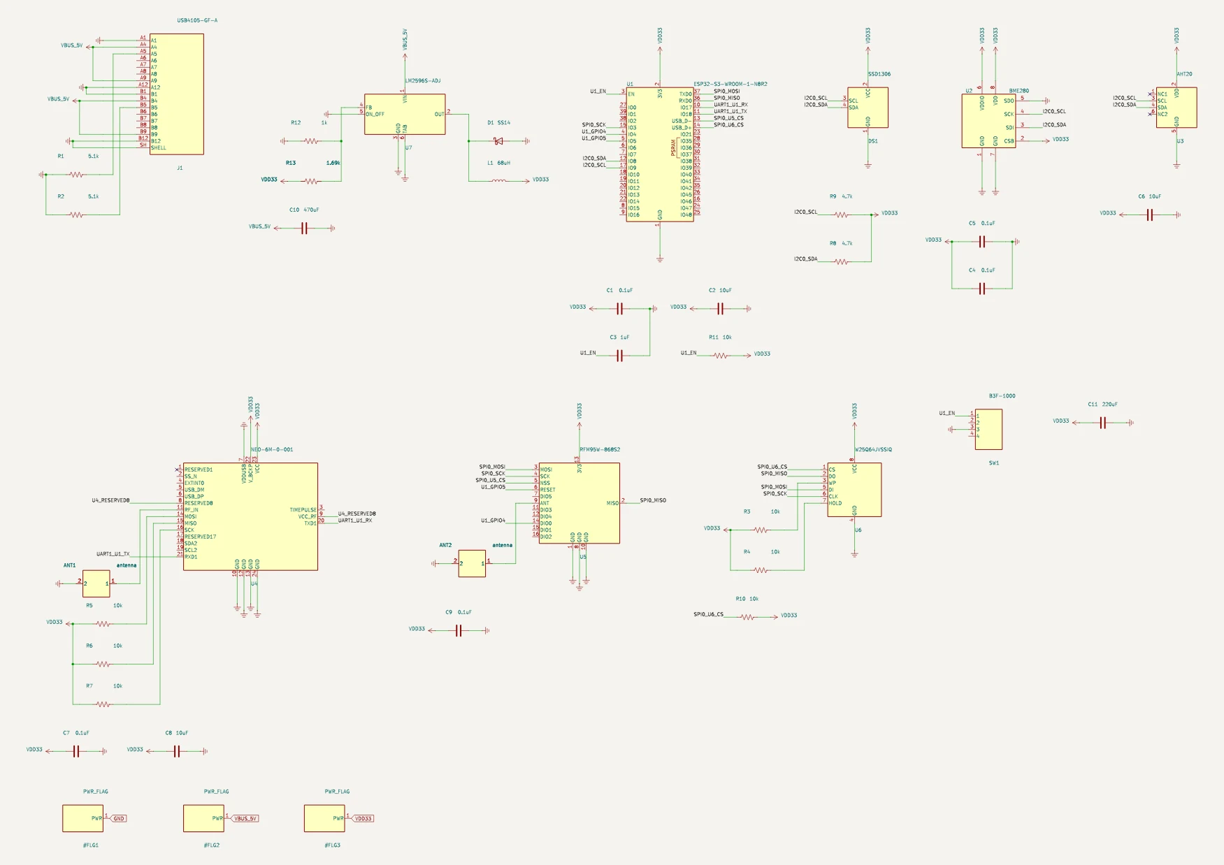
A solar field logger schematic compiled by Typmax: an ESP32-S3, two environmental sensors on I²C, an OLED, a GPS module, a LoRa radio, onboard flash and a switching regulator, drawn as a KiCad sheet.
A field logger with a LoRa uplink — rendered from the .kicad_sch Typmax wrote, not a mock-up. Open the full sheet →
.kicad_sch
the schematic
.kicad_pro
the project
netlist
what connects to what
BOM
every part, to order
report
every check, with its maths
The report

Four things wrong with the board above.

The 3.3 V supply is specified to hold a tighter window than the regulator's own feedback resistors can actually deliver at their tolerance corners — so every check downstream was computed against a voltage the board never guarantees.

The radio's chip-select pin floats while the processor is still booting, so the radio can select itself and treat whatever the boot ROM happens to be doing as instructions. And the diode protecting the regulator is rated for a third of the current the regulator can push through it.

None of that is visible by looking at the drawing. All of it is arithmetic against the datasheets — and each one is a board you paid for and cannot use.

How the checking works →

board › solar field logger, lora uplink
power.rail_source_toleranceFAIL
Rail VDD33 declares 3.251 V–3.349 V but U7 (ti/lm2596s-adj) holds 3.135 V–3.487 V (params.v_ref × (1 + R_FB2/R_FB1) at the resistors' tol_pct corners): declared min 3.251 V is ABOVE the source floor 3.135 V;…
swreg.catch_diode_ratingWARN
D1 (vishay/ss14) as catch diode for U7: I_F(AV) 1 A < the regulator's current limit 3.6 A — a sustained output short is not survived.
spi.cs_default_stateFAIL
U5.NSS floats while the controller is in reset/boot: no resistor to a rail on the derived net, no internal pull in the record.
swreg.ripple_ratioWARN
L1: inductor ripple 17.432 percent of I_out (0.11 A / 631.006 mA) below the 20 percent–40 percent guideline — the inductor is larger/slower than the load needs.
4 of 126 checks shown · 86 pass · 4 warn · 3 error · 32 not computabledesign-10b5c755376f

For comparison, KiCad’s own electrical rule check runs on this same file and reports 50 violations — 46 of them simply pins nobody wired. Both tools are right; they are answering different questions. ERC asks whether the drawing is wired. Typmax asks whether the numbers work.

The product

Generate it. Check it. Change it.

Four things, in the order we're building them. Three of them work today.

01TODAY

Generate

Describe the board in a sentence. Get a schematic built from parts that exist, that you can buy.

02TODAY

Check

Every number checked against the datasheet it came from — pull-ups, rail budgets, logic levels, decoupling, missing connections.

03TODAY

Change

Swap a part, move a pin, raise the bus speed. Edits are small and surgical — what you fixed stays fixed, and everything is re-checked.

04NEXT

Lay out

The board itself — placement and routing, with the electrical checks re-run on real trace lengths instead of assumptions.

Bringing a schematic you already have is on the way too — what works today.

How it works

The AI plans. It doesn't hold the pen.

Ask a language model to draw a circuit from memory and it will drop a pull-up and never notice. So it doesn't get to draw. It only proposes changes — "add this part, connect that pin" — and code that reads datasheets does the rest.

01 · YOU

Describe it

"ESP32-S3, a BME280 sensor, GPS, running off a 3.3 V rail."

02 · THE MODEL

Plans the edits

Small, reversible steps. It never writes a file and never remembers your design.

03 · THE ENGINE

Engineers it

Real part records, wiring by rule, every value computed and cited — never recalled.

04 · YOU, AGAIN

Open it in KiCad

Your files, your board. Plus the report saying why each check passed — or didn't.

488
part records, read from their datasheets
294
faults deliberately planted, to prove the checks catch them
34
interfaces whose rules cite the app note they came from

Counted from the repository on 10 September 2026. We publish the numbers as they move.

Worked examples

Six boards, every check run.

Real designs the engine compiles and checks today. Every number below came out of the engine on this build — none of it is typed by hand, and the page goes red in CI if it drifts.

The solar field logger, lora uplink schematic, compiled by Typmax

Solar field logger, LoRa uplink

An ESP32-S3 logging two environmental sensors to onboard flash, showing them on an OLED, fixing its position by GPS and reporting over a LoRa radio — all off a switching regulator.

ESP32-S3-WROOM-1-N8R2, BME280, AHT20, SSD1306

126 checks · 86 pass · 4 warn · 3 error

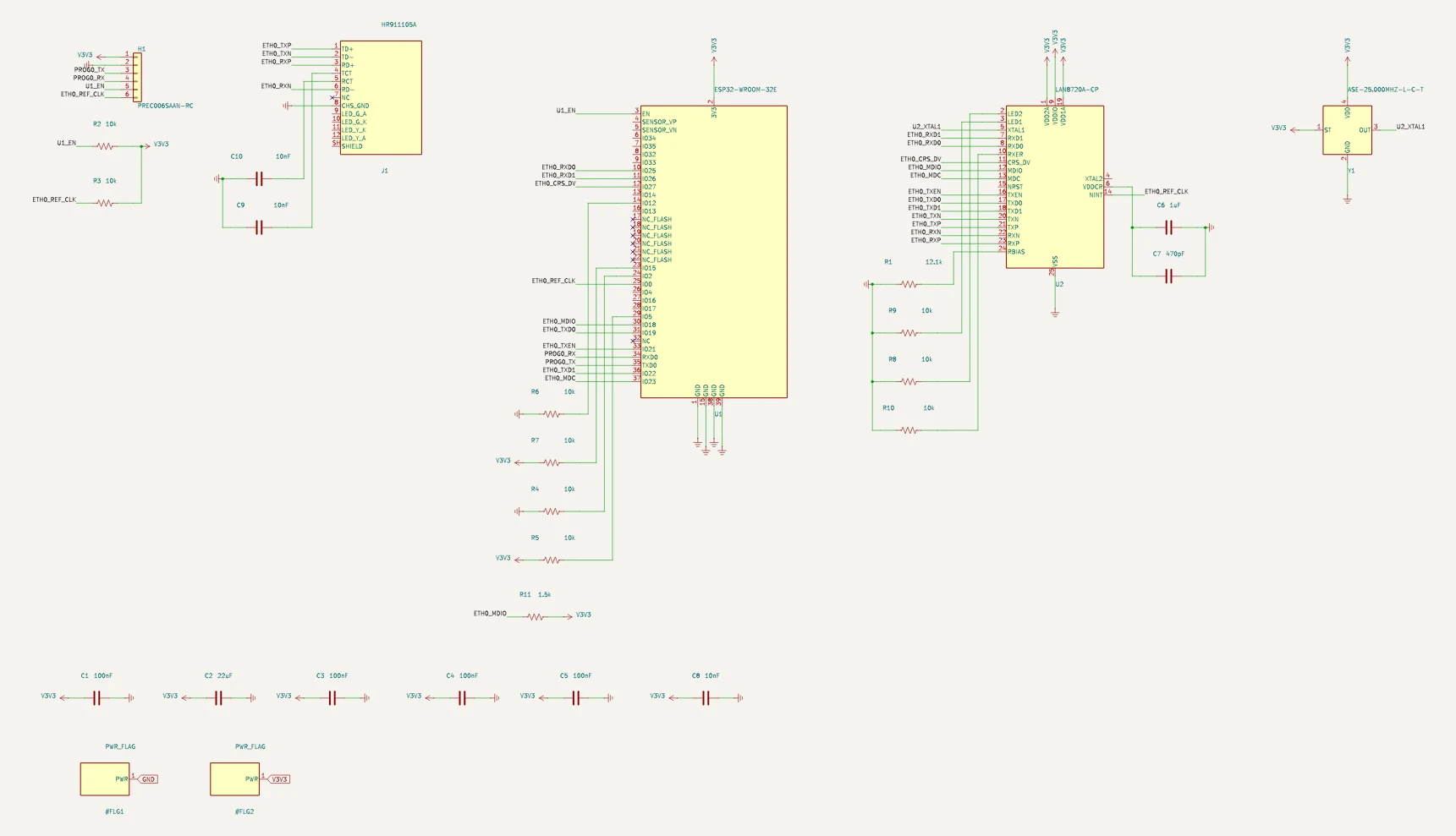
The wired ethernet schematic, compiled by Typmax

Wired Ethernet

An Ethernet PHY and its magnetics, with the impedance-controlled pairs the standard requires.

ESP32-WROOM-32E, LAN8720A-CP, HR911105A, ASE-25.000MHZ-L-C-T

89 checks · 69 pass · 1 warn · 0 error

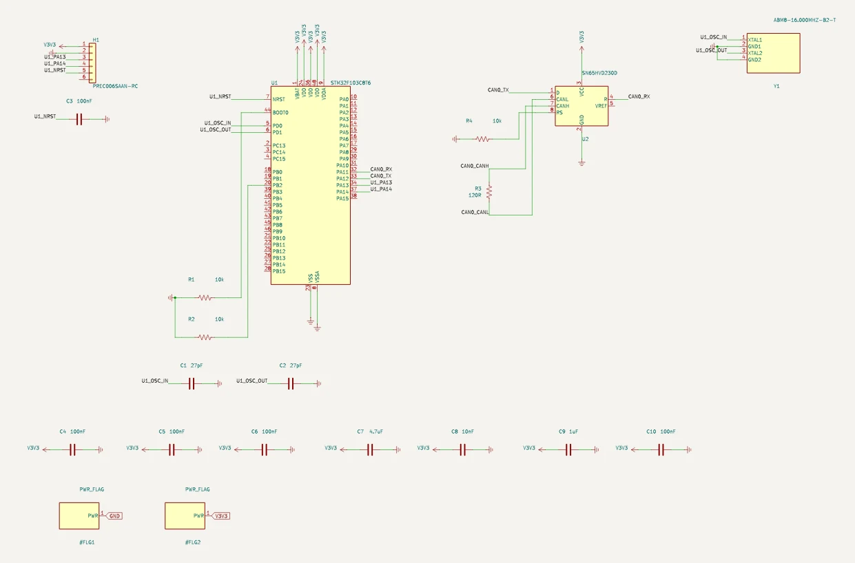
The can bus node schematic, compiled by Typmax

CAN bus node

A CAN transceiver on a vehicle bus, with the termination and common-mode handling the topology needs.

STM32F103C8T6, ABM8-16.000MHZ-B2-T, PREC006SAAN-RC, SN65HVD230D

45 checks · 38 pass · 0 warn · 0 error

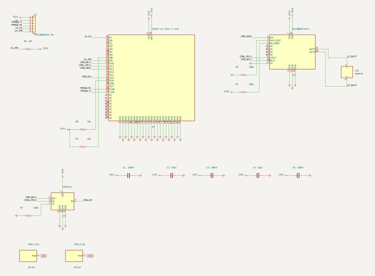
The digital audio schematic, compiled by Typmax

Digital audio

An I²S audio path — the clock, word-select and data lines that carry sound between chips.

ESP32-H2-MINI-1-H4S, MAX98357AETE+, INMP441, PREC006SAAN-RC

46 checks · 36 pass · 0 warn · 0 error

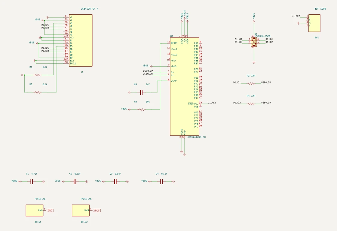
The usb-c power in schematic, compiled by Typmax

USB-C power in

A USB-C sink: the configuration-channel resistors that tell the charger how much current to offer, plus ESD protection.

ATMEGA32U4-AU, USB4105-GF-A, USBLC6-2SC6, B3F-1000

34 checks · 24 pass · 1 warn · 0 error

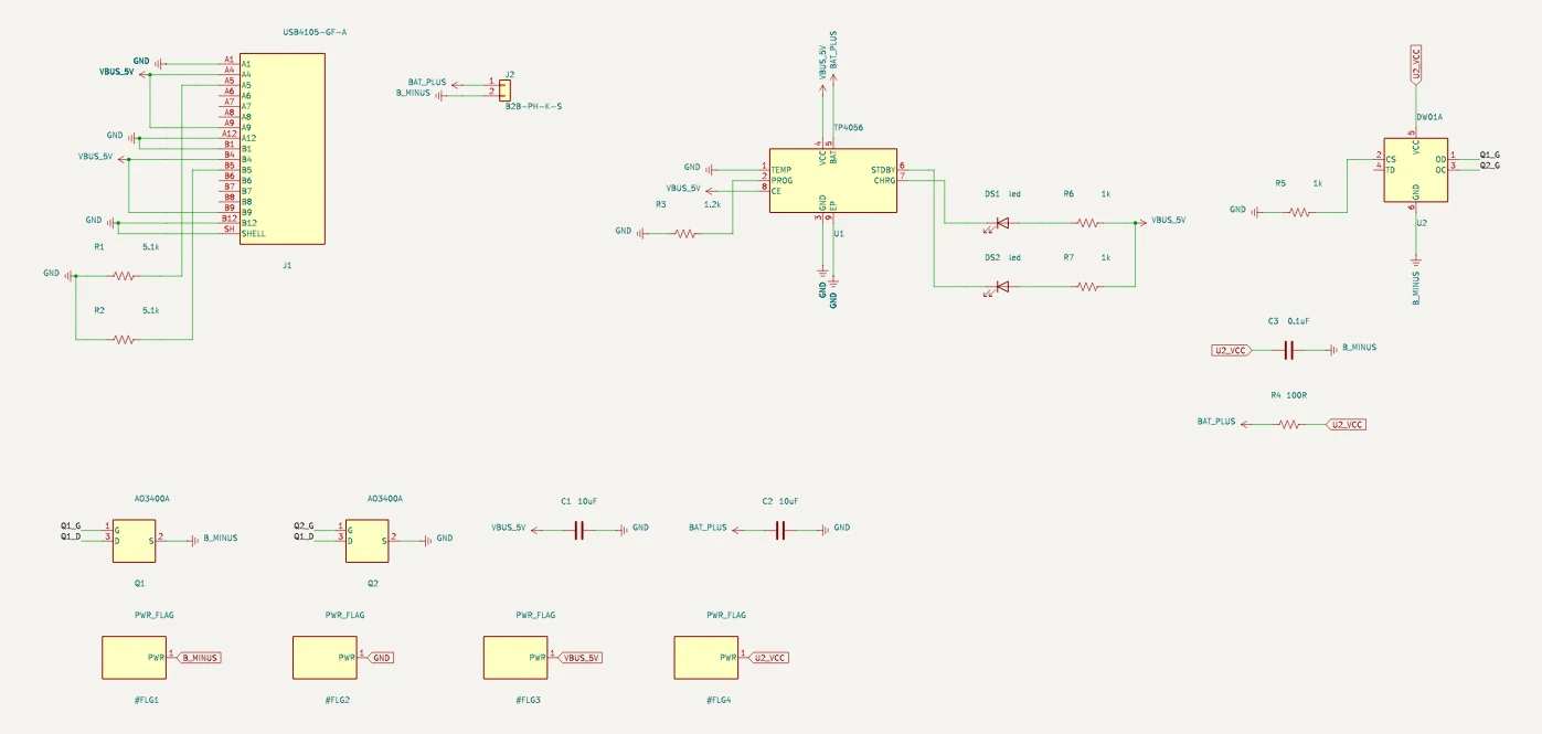
The single-cell lipo charger schematic, compiled by Typmax

Single-cell LiPo charger

A lithium battery charger — a risk domain, so it ends in human review no matter how many checks pass.

USB4105-GF-A, TP4056, DW01A, AO3400A

37 checks · 16 pass · 2 warn · 2 error

The LiPo charger ends in human review however many checks pass — battery, mains and motor drive always do.

Straight answer

What it can't do yet.

We'd rather you read this here than find out on a board.

It stops before the PCB

You get the schematic and the project. Placing and routing the board is still yours — for now.

It won't invent a circuit

It assembles known parts and proven sub-circuits. A novel analog front end is not what this is.

Anything dangerous ends with a human

LiPo charging, mains, motor drive: it runs every check it has, then tells you a person has to sign it off. That never gets softened.

The rest of the honest answers →

Waitlist

Tell us what you're building.

Seats open in small batches as the catalog grows — and the parts you name go to the front of the queue to be checked against their datasheets.

01Early access, in small batches
02Name the parts you want checked first — they jump the queue
03The weekly changelog — follow the build as it lands
Join the waitlist

No spam. The weekly changelog, and one email when your seat opens.

Or just ask

Bring a board you're stuck on and get an honest read on whether Typmax helps yet — a reply from me, not a form.

[email protected]