ERC clean is where the checks start.
A desk robot whose USB rail is six times over budget. A radio whose chip select floats during boot. A board you can never flash. All three pass KiCad's electrical rules check.
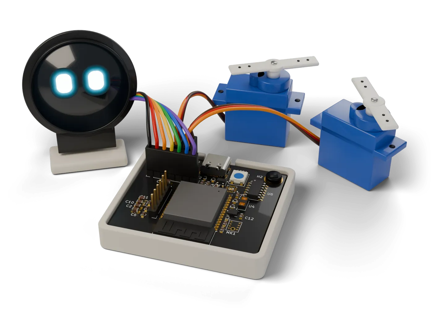
Two weeks ago I described a desk robot to the tool I'm building. Two servos, a round display, a microphone, a little speaker, an ESP32-S3 to run it, one USB-C port for power. Plain English, one paragraph. It picked the parts, wired them by rule, and the first line of the report was a FAIL.
I'd have ordered that board. I've ordered worse.
The line ERC can't see
The 5 V rail summed to 2,542 mA from the parts' own records. With the 1.3 margin the power rule applies, 3,305 mA. A laptop USB port promises 500 mA. Six and a half times over, before the first servo moves.
The 5 V rail asks for 3,305 mA. The port promises 500 mA.
Here's the thing. That schematic passes ERC. Every pin is connected, every net has a source, no two outputs fight. KiCad's electrical rules check is a connectivity check and a good one, but it has never read a datasheet. It cannot know that a stalled SG90 can pull over 800 mA, or that a port is a port.
The part of that report I like most is the last line. It says which number nobody has verified yet: the servo's stall current, which no vendor sheet actually states. The record carries a spread of bench measurements and says so. If you doubt the finding, you know exactly where to look.
A check that hides its inputs is just another opinion.
The board I keep breaking
The field logger has been my test board since the summer. An ESP32-S3, a LoRa radio and a flash chip on one SPI bus, a buck regulator, a few sensors. It's on its sixth revision. It's the design I throw at every new rule, and it keeps paying out.
Two findings from it, both on a schematic with zero ERC violations.
The radio's chip select floats during boot. NSS is wired to a GPIO. Connected, driven, fine. Except the MCU holds its pins high-impedance for the first stretch after reset, there's no pull-up on that net, and the radio's record says it has no internal pull either. So for a hundred milliseconds or so the radio can latch itself selected and clock whatever the boot ROM puts on MOSI into its own registers.
The radio's chip select floats while the MCU is in reset.
On the drawing it's a wire from a pin to a pin. The bug is about what the pin does before firmware exists, which is a question about the part, not the wire. Nobody finds this one on the bench quickly either. It looks like a flaky radio driver.
You can never flash it. Same board, same revision. The UART pins had been bound to the SPI bus, and neither boot strap reached a connector, a switch or a test point. Every pin connected. Nothing you could plug a programmer into.
No programming path is complete. Firmware cannot be loaded onto this board as drawn.
This is the one that embarrasses me, because it's not subtle. A reviewer with coffee would catch it. But the reviewer with coffee is the step everyone skips when the demo says "ERC clean" and the fab is a click away.
The smaller ones
Not every finding is a disaster. Two from the same files that I'd still want to know before ordering:
The buck regulator's catch diode is an SS14, rated 1 A average. The regulator's current limit is 3.6 A. A sustained short on the output and the protection part is the first thing to die.
A GPS module's RF_IN pin had nothing on it. The record marks it must-connect. No antenna path, no fix, just a module that would never get a lock and a long afternoon on the roof.
What ERC said about the same file
We ran KiCad's ERC on the same field logger file, to be fair to it. It reports 50 violations, and they're real: worth fixing, all of them. None is the chip select, and none is the programming path.
You don't need a tool for this
You need the rule and the numbers, and the discipline to do it every time. If you want to do it by hand before your next order:
- Sum the rail. Every supply pin on it, the peak row from each datasheet, then compare to what the source actually delivers. For USB that's 500 mA unless you've done the CC negotiation.
- For every chip select, reset and enable, ask what state it's in before firmware runs. If the answer is "whatever the pull decides" and there's no pull, that's the bug.
- Trace the programming path with a finger. From the UART or USB pins of the MCU to something you can physically touch, plus the boot strap. If the finger doesn't arrive, you won't either.
- Any part described as protection: check its rating against the thing it's protecting against, not the normal load.
That's most of what my tool does on these boards. It's not clever. It's a datasheet held open next to the netlist, every single time, without getting bored.
What I'm building
Typmax is that, as software. You describe the board in plain English. The model only proposes small edits. Deterministic code picks real parts, wires by rule and runs the checks, and every check prints the number it computed, the rule it applied and where the rule came from, usually a vendor app note we keep as data rather than code. The model never writes the KiCad file. The files are yours: schematic, project, netlist, BOM, a placed board.
What it doesn't do yet, so you don't find out later.
It places parts; you route. No manufacturing files. One of 499 catalog records is human-verified; the rest are machine-read from datasheets and tagged that way, and every report names the inputs nobody has checked. Battery, motor and mains boards always end in human review, on purpose.
If you have a board that passed ERC and surprised you at bring-up, I'd like to hear about it: [email protected]. And if you want yours checked this way, request early access. The parts you name get verified first.